Ultimaker 3D Printer

Tutorial designed by: Kit Lo, Innovation Wing tutor

Usage arrangement

FOR ALL
MEMBERS

Access
permission

CHECK-IN-OUT
WITH STAFF

Requirement
before usage

WITH

TUTORS

Buddy system
requirement
  1. [For All Members] All members of Innovation Wing are welcome to use the Ultimaker 3D printer to support their hands-on works.
  2. [Talk to us] Before using our 3D printers, please let us know your print job and project works by filling the 3D Printing Job Registration Form. If you do not have a project supervisor, please contact our staff (Director of Innovation Wing/ technical staff/ tutor staff), we are very happy to help you.
  3. [Operate the 3D printer with tutors/technicians] Please operate the 3D printer with our tutors/technicians, we are very happy to help.
Usage procedure for members
  • Step 1. Create object model (.STL file)

    Use any object modeling software (e.g., Solidworks / Fusion 360) or download a 3D model online for printing. Prepare the object model in .stl file format.

  • Step 2. Printing pre configuration (.G-code file)

    Use Ultimaker Cura software to do pre-configuration of the print job. Do slicing and obtain the estimated printing duration and estimated material for the print job. Download the g-code file into a USB drive.

  • Step 3. Talk to on-duty tutor/technician

    Come to Innovation Wing and talk to any of our on-duty tutors/technicians. They will go through the printing file with members and do a final confirmation of the printing parameters (such as duration, layer thickness, dimension, ...etc) 

  • Step 4. Fill in the job registration form by members

    Once confirmed, members can fill the 3D printing registration form.

    Note: Printing jobs without a valid registration will be stopped immediately by staff. Printed items without a valid registration will not be collected by any members.

  • Step 5. Submit the print job to the 3D printer by tutor/technician (NOT by member)

    The tutor/technician will check the registration record and once the data are verified, the tutor/technician will operate the 3D printer and submit the job with the presence of the student member.

  • Step 6. Start printing and collection of printed items

    Member please come to Innovation Wing to collect the printed items. Members are encouraged to come to check the printing process frequently as there is NO GUARANTEE that the print job will be successful. 

    Printed items that are not collected for a week will be removed by Innovation Wing staff.

3D printing registration form
  • Members please come to Innovation Wing and talk to our on-duty tutors/technicians.
  • Innovation Wing tutor/technician will go through the printing file with members and do a final confirmation of the printing parameters (such as duration, layer thickness, dimension, …etc) 
  • Once confirmed, members can fill the 3D printing registration form

  • Innovation Wing tutor/technician will mark the assigned timeslot for the 3D printer on calendar.
User manual of Ultimaker 3

Please click the following button to access the official user manual for Ultimaker 3 printer.

Safety rules

All users of this machine should read the following session about safety carefully before operating the machine.

The following are recapped from the user manual of the Ultimaker S3 printer.

1. General safety information

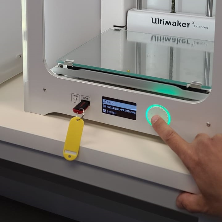
  • Ultimaker 3D printers generate high temperatures and have hot moving parts that can cause injury. Never reach inside Ultimaker 3D printers while they are in operation. Always control the printer with the touchscreen at the front of the power switch at the back. Allow the Ultimaker 3D printers to cool down for 5 minutes before reaching inside.
  • Do not change or adjust any parts of the products unless the change or adjustment is authorized by the manufacturer.
  • Do not store items inside Ultimaker products.
  • Ultimaker products are not intended for use by persons with reduced physical and/or mental capabilities, or lack of experience and knowledge unless they are supervised or have been given instructions concerning the use of the appliance by a person responsible for their safety
  • Children should be under constant supervision when using Ultimaker products.

2. Hazards

Electromagnetic compatibility (EMC)

These devices may not cause harmful interference, and these devices must accept any interference received, including interference that may cause undesired operation.

An electrostatic discharge in some metallic parts of the devices may cause the interruption of the NFC communications, affecting the initial detection of the material spool. In these cases, a device restart should solve the problem

Electrical safety

  • Ultimaker products have been tested according to the IEC 60950-1 and/or IEC 62368-1. All relevant products have undergone and passed hi‐pot testing before shipment. This test guarantees the right level of insulation
    against electrical shock. An earthed mains socket must be used. Be sure that the building installation has dedicated means for over-current and short-circuiting. For more information, please visit the official website for the CB-certificate. The Ultimaker 3D printers are powered by mains voltage, which is hazardous when touched. Only trained staff should remove the bottom cover.
  • Always unplug Ultimaker products before performing maintenance or modifications.

Mechanical safety

  • Ultimaker products are compliant with the Machine Directive 2006/42/EU. The EC declaration of conformity can be found on our website. The Ultimaker 3D printers contain moving parts. No damage to the user will be expected from the drive belts. The force of the build plate may cause minor injury, so stay out of the reach of the build plate during operation.
  • Always unplug the product before performing maintenance or modifications.

Risk of burns

  • There is a potential risk of burns: the print heads of the Ultimaker 3D printers can reach temperatures above 200 °C, while the heated bed can reach temperatures above 100 °C. Do not touch either of these parts
    with your bare hands.
  • Always allow the product to cool down for 30 minutes before performing maintenance or modifications.

3. Health and safety

  • 3D printing thermoplastics may result in the release of ultrafine particles (UFPs) and volatile organic compounds (VOCs) depending on the thermoplastic used and settings of the 3D printer.
  • Ultimaker products are designed for use with Ultimaker materials and are open for use with materials from third-party suppliers.

4. Operation

  • Do not touch the contact points on the back of the print core with your fingers.
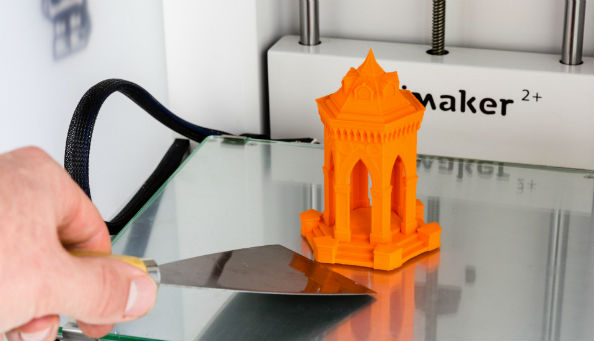
  • When using a brim, be aware of the danger of cutting yourself when removing the print from the build plate. Use a deburring tool to remove the brim once the print is taken from the build plate.
  • Take the build plate out of the printer to avoid damaging the build plate clamps.
  • It is advised to wear protective gloves when the support structure contains sharp corners or when working with larger models.
  • Do not touch the contact points on the backside of the print core with your fingers.

5. Calibration

  • Make sure there is no excess material below the tip of the nozzles and the build plate is clean before the start of a print or when you want to calibrate the build plate, or you might get inaccurate results.
  • Do not touch the Ultimaker during the active leveling procedure, as this could affect the calibration process.
  • Do not apply force to the build plate while fine-tuning with the calibration card, as this will lead to leveling inaccuracies.
Operational guideline (to be completed by tutor/technician)

This operational guideline is a walkthrough of the general printing procedure in Innovation Wing. You will act as a member and go through this process once.

  • Step 1. Create an object model (.STL file)
  • Step 2. Printing pre-configuration (.G-code file)
  • Step 3. Talk to on-duty tutor/technician staff.
  • Step 4. Fill in the job registration form by members, mark on the usage calendar by staff
  • Step 5. Start printing and collection of printed items.

Step 1. Create an object model (.STL file)

  • Members can do this part on their own computer/ in the digital learning studio.
  • This is not a tutorial of Solidworks.
  • 1.1. Open Solidworks from any computer in Innovation Wing (Our members can do it in the digital learning studio, they may also use other 3D modeling software like Fusion 360).
  • 1.2 In the Welcome panel, choose Part, as we are only using the Solidworks to draw a 3D part (there are many other features like assembly and simulation that you have to learn in other Solidwork workshops if you are interested in)
  • 1.3. Once the workspace is loaded, click the “Top Plane” on the left panel to view the top panel of the workspace (As in the 3-dimension, there are actually 6 faces).
  • 1.4. It is easier for us to draw the shape if we have a top view. Click on the “View Orientation” button as illustrated in the figure.
  • Choose the “Top” view orientation
  • 1.5. This is what looks like if you see the workspace from top orientation.
  • 1.6. Sketch is the first step to draw a shape because we want to make a rectangle as the base.
  • Please click the Sketch tab, then choose the Corner Rectangle button.
  • 1.7. Use the mouse to click and drag a rectangle, dimension around 90mm width and 58mm height. You do not need to be precise at this step.
  • After drawing the rectangle, we have to click the green tick to confirm the shape. 
  • 1.8. Now we would like to use the Smart Dimension tool to fix the dimension of the rectangle.
  • Click the “Smart Dimension” button on top.
  • Click the top edge of the rectangle and the measurement is listed.
  • Then you can key in the length as 90mm.
  • Remember to click the green tick to commit the change.
  • 1.9. Now you can repeat Step 1.8 on the other dimension of the rectangle to set it as 58mm.
  • 1.10. Now we would like to use add the extruded feature for the rectangle (from 2D to 3D)
  • Click the “Features” tab.
  • Click the Extruded Boss/Base button
  • 1.11. We can key in the thickness (or Depth) of the layer as marked in the red textbox. 
  • Let’s set it as 2mm 
  • Commit the update by clicking the green tick.
  • 1.12. You can see the object is now a thin 3D rectangle.
  • To make the corner of this 3D rectangle round shape, please click on the “Fillet” button on top.
  • 1.13. After clicking the fillet button, you can specify the items to Fillet.
  • The items to Fillet are the 4 edges of the rectangle. 
  • Use mouse to carefully highlight the 4 edges. Note that we should select the short lines as marked by red circles in the figure.
  • Once the 4 edges are selected, click the green tick to apply the fillet feature.
  • 1.14. This is the finished object after successfully apply the fillet feature on the 4 edges.
  • 1.15. Now we would like to add text on top of the rectangle. Let’s change the view orientation back to top.
  • 1.16. This figure shows the top view of the current object.
  • Click on the surface to mark the face we are applying the text on.
  • Then click on the “A” text button on the top to start key in the text to attach to the surface.
  • 1.17. Now key in the text “INNOWING
  • Uncheck “Use document font” so you can choose your own font.
  • Click the Font button to choose the font and size you want.
  • Let’s use the Front height of 40
  • Click ok to confirm the font, and click the green tick to apply the Text.
  • 1.18. Use the mouse to move the Text to the middle top area of the rectangle.
  • 1.19. Now we have the “INNOWING” text on the rectangle.
  • We are going to make the “INNOWING” 3D and level up.
  • To do this, again we click on the “Features” tab.
  • Click the Extruded Boss/Base button
  • 1.20. We can key in the thickness (or Depth) of the layer as marked in the red textbox. 
  • Let’s set it as 1mm 
  • Commit the update by clicking the green tick.
  • 1.21. Let’s view the 3D object by changing the view orientation to Isometric.
  • 1.22. The isometric view of the 3D model.
  • 1.23. Now it is your turn to add your nickname to the middle bottom part of the rectangle. Please repeat step 1.15 to do this.
  • 1.24. Once the object is done. Let’s Save as
  • 1.25. Choose STL type as the next step requires .STL file for 3D printing.
  • Note that you have to save the entire project into “SOLIDWORKS Part” type so you can do the editing with solidwork in the future.

Step 2. Printing pre-configuration (.G-code file)

  • Members can do this part in their own computer/ in the digital learning studio.
  • 2.1. Open the Cura software application. The Cura software is installed in all computers in the digital learning studio and the computers next to the 3D printers. The version we used in this tutorial is 4.8.0.If you use another version, please use the following screen cap figures as a reference.
  • 2.2. Load the .stl file of the 3D object. 
  • 2.3. The object will be loaded and show on the interface. Click on the object to edit the orientation, scaling, and other parameters. 
  • 2.4. Rotation. Click on the “Rotation” button as illustrated in the following figure, you will see the rotation can be on X,Y,Z dimension.
  • 2.5. Try to click on the “red” dimension and drag downward to make the words on the object facing upward.
  • 2.6. This figure shows the object after rotation.
  • 2.7. Scaling. Change the printing dimension of the object.
  • Let’s try to click on the scale button and change the X-dimension from 90mm to 45 mm. You will see the object becomes much smaller.
  • 2.8. Setup printing parameter. Click the custom button as shown in the following figure. 
  • 2.9. There are two extruders in Ultimaker, select “1” and set the material as PLA and print core as AA 0.4.
  • 2.10. Ultimaker has dual extruders that you can print two materials on a single print. To learn more about dual extruders, you may refer to the above Youtube tutorial.


  • 2.11. Click on the print settings. Here you can select the printing profile which you can customize:
    • Please choose the layer thickness as 0.2 mm
    • infill (%)  as 10%
    • No need support material
    • No need Adhesion
  • You may learn more about the parameters through the above tutorial.
  • 2.12. Once the setting is ready, click slice which will generate a g-code file ready for printing. 
  • 2.13.  There will be time estimation and material estimation and save to file you need to submit when you apply for printing in Innovation Wing in the next step.

Step 3. Talk to Innovation Wing tutors/technicians

CHECK IN-OUT
WITH STAFF

Requirement before usage

  • 3.1. Members come to Innovation Wing and talk to our tutors/technicians.
  • 3.2. Innovation Wing tutor/technician will go through the print file and double confirm the printing parameters and materials (such as layer height, in-fill, support, etc.).

Step 4. Fill in the job registration form by members

  • 4.1. After confirming the print job, members will fill in the 3D printing registration form.
  • Note: tutors and technicians who go through this tutorial, please also fill in the form once and fill the following info:
    • Please use your name and student/staff ID
    • Project supervisor as “Innovation Wing”
    • Supervisor email as “innowing@hku.hk”
    • Project type please select “Training – Work on the training material”.
  • 4.2. Tutor/technician will check received registrations. (Please use the login account mentioned in the staff training workshop to check the following registration list.)

Step 5. Start printing and collection of printed items

WITH TUTORS

Buddy system requirement
  • Tutor/technician will submit the print job to the Ultimaker and assist with operating the machine.
  • 5.1 Click the Cura software “Save to File”  and save it to a USB thumb drive.
  • Unplug the USB thumb drive and insert it into the Ultimaker 3D printer.
  • 5.2. Please check if we should load/unload materials.
  • 5.3. Submit print job to Ultimaker and start printing. Use the circular button in the front to select PRINT, and then select the file to print. Ultimaker will start printing.
  • 5.4. After collecting the printed object, please show this to the technical manager (Seto) for recording the completion of this tutorial.
  • 5.5 Please put the printed object inside your tutor/technician badge when you are on-duty 😉

To seek help and assistance

  • Please try to troubleshoot by yourself first by reading the user manual.
  • Seek help from other tutors and technicians if needed.
  • Approach the technical manager if you have questions about machine operation, maintenance, and usage rules.
Loading / unloading printing filament

Loading printing filament for Ultimaker 3 extended.

Unloading printing filament for Ultimaker 3 extended.

Acknowledgment
  • This tutorial is prepared by our tutor Kit Lo from the Innovation Tutorship Training Scheme on Dec 2020.
  • This tutorial is edited by CS Seto (technical manager of Innovation Wing), Edison (technical staff of Innovation Wing) on Jan 2021.
  • Materials from this tutorial include some recap of the official user manual from Ultimaker. With some additional materials added by our staff.
Facts
  • Ultimaker is a leading brand in the 3D printing industry, known for producing high-quality, reliable machines.
  • Ultimaker printers use Fused Filament Fabrication (FFF) technology, also known as Fused Deposition Modeling (FDM), which involves melting and extruding thermoplastic materials to create 3D objects layer by layer.
  • Ultimaker printers are highly customizable, with a range of options for nozzle size, print speed, and other settings that allow users to optimize their prints for specific applications.
  • Ultimaker printers come with a user-friendly software called Cura, which provides easy-to-use slicing and printing controls for users of all levels.
  • Ultimaker printers are used in a variety of industries, including automotive, aerospace, education, and healthcare, to create prototypes, functional parts, and other 3D printed objects.
Agenda

SIG – HKU Racing

Formula Student is a renowned educational engineering competition, combining practical engineering with soft skills including business planning and project management. It is a proving ground for students who want to create and change the world. Electrification of transportation system is here, the combination of electric powertrain and traditional mechanical system has made this competition attractive to lots of industries leading to companys’ attention and support. This competition jump starts our students’ knowledge and skills set for their future career. HKU Racing is the first team from Hong Kong to compete in Formula Student (European series).

Read More »

BREED Robotics (Official)

BREED is a student group committed to developing and promoting bio-inspired technology. Our flagship VAYU project – the world’s fastest robotic fish – and our upcoming initiatives such as our robotic dog aim to educate and enhance awareness in the general student body. Using designs perfected by millions of years of natural evolution, we adapt selected features into increasing effectiveness of man-made robots. We aim to establish a hub based in the Innovation Wing where this development can take root in the local community, increasing awareness and interest while promoting scientific innovation: this will be done through outreach projects, educational initiatives, as well as the continuation of various bio-inspired initiatives under BREED.

Read More »

Acrylic laser cutting and engraving machine

An acrylic laser cutting and engraving machine is a powerful tool for creating high-precision designs in acrylic materials. These machines use a high-powered laser to cut and engrave designs onto acrylic sheets, resulting in intricate and detailed finished products. Acrylic is a popular material for laser cutting and engraving due to its versatility, durability, and transparency. With a laser cutting and engraving machine, users can create a variety of products, including signage, jewelry, awards, and decorative items. These machines typically offer a range of settings to adjust the laser’s power and speed, allowing for precise control over the cutting and engraving process.

Read More »
For Inquiries, Please Contact

Please contact

    • Natalie Chan (natcychan[at]hku.hk), the teaching assistant of the Tam Wing Fan Innovation Wing, or
    • Ryan chan (ryancck[at]hku.hk), the senior technical assistant of the Tam Wing Fan Innovation Wing